 한컴오피스
한컴오피스 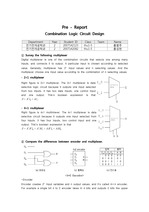
-
미리보기
소개
연세대학교 전기전자기초실험 예비 래포트입니다. 누구한테 준 적 없는 자료이구요 ~ A0 받았습니다 ~~목차
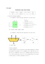
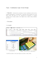
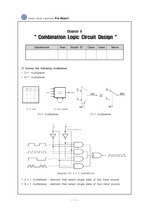
① Survey the following multiplexer
② Compare the differences between encoder and multiplexer.
③ Compare the differences between decoder and multiplexer.
④ Compare the differences between decoder and encoder.
⑤ Survey other types of decoder.
⑥ Survey either of 7446, 7447, 7448 elements
⑦ Express 7-segment controller using verilog HDL.본문내용
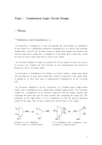
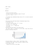
-Encoder
Encoder creates input variables and n output values, and its called m×n encoder. For example a single bit 4 to 2 encoder takes in 4 bits and outputs 2 bits like upper figure. The encoder has the limitation that only one input can be active at any given time. If two inputs are simultaneously active, the output produces an undefined combination. To prevent this we make use of the priority encoder. A priority encoder is such that if two or more inputs are given at the same time, the input having the highest priority will take precedence.
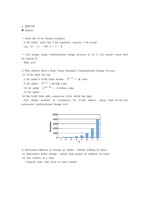
-Multiplexer
Digital multiplexer is one of the combination circuits that selects one among many inputs, and connects it to output. A particular input is chosen according to selected value. Generally, multiplexer has input values and n selecting values. And the multiplexer choose one input value according to the combination of n selecting values.참고자료
· 없음태그
-
자료후기
 Ai 리뷰지식판매자의 자료는 항상 기대 이상의 정보를 제공합니다. 특히 학업에도 활용할 수 있어 매우 만족스럽습니다. 여러분께도 추천합니다!
 -
자주묻는질문의 답변을 확인해 주세요

꼭 알아주세요
-
자료의 정보 및 내용의 진실성에 대하여 해피캠퍼스는 보증하지 않으며, 해당 정보 및 게시물 저작권과 기타 법적 책임은 자료 등록자에게 있습니다.
자료 및 게시물 내용의 불법적 이용, 무단 전재∙배포는 금지되어 있습니다.
저작권침해, 명예훼손 등 분쟁 요소 발견 시 고객센터의 저작권침해 신고센터를 이용해 주시기 바랍니다. -
해피캠퍼스는 구매자와 판매자 모두가 만족하는 서비스가 되도록 노력하고 있으며, 아래의 4가지 자료환불 조건을 꼭 확인해주시기 바랍니다.
파일오류 중복자료 저작권 없음 설명과 실제 내용 불일치 파일의 다운로드가 제대로 되지 않거나 파일형식에 맞는 프로그램으로 정상 작동하지 않는 경우 다른 자료와 70% 이상 내용이 일치하는 경우 (중복임을 확인할 수 있는 근거 필요함) 인터넷의 다른 사이트, 연구기관, 학교, 서적 등의 자료를 도용한 경우 자료의 설명과 실제 자료의 내용이 일치하지 않는 경우
찾으시던 자료가 아닌가요?
지금 보는 자료와 연관되어 있어요!

-
공학/기술

- Combination Logic Circuit Design
- *성* | 6 페이지
- 1,500원
-
공학/기술
- 전기전자기초실험 Combination Logic Circuit Design 결과레포트 (영어)
- *지* | 7 페이지
- 1,000원
-
공학/기술
- Combination Logic Circuit Design
- *성* | 6 페이지
- 1,000원
-
공학/기술
- 전기전자기초실험 Combination Logic Circuit Design 예비보고서
- *효* | 13 페이지
- 1,000원
-
공학/기술
- 전기전자기초실험 Combination Logic Circuit Design 결과보고서
- *효* | 10 페이지
- 1,000원

-
공학/기술
- [검증된 코드 & 복사가능, 학점A+] 전전설2 6.Sequential-1 - 예비+결과+성적인증 (서울시립대)
- 정신좀 | 22 페이지
- 3,500원
판매자 설정표지

-
공학/기술
- Semiconductor Device and Design - 8_
- leejhuek | 18 페이지
- 2,000원

-
공학/기술
- 서울시립대 전전설2 Lab-03 예비리포트 (2020 최신)
- 러블리즈 | 13 페이지
- 1,500원
판매자 설정표지

-
공학/기술
- 서강대학교 21년도 디지털논리회로실험 3주차 결과레포트 (A+자료) - Decoder, 7-Segment Display
- 샛여우 | 34 페이지
- 2,000원

-
공학/기술
- 서울시립대 전전설2 Lab-03 결과리포트 (2020 최신)
- 러블리즈 | 19 페이지
- 1,500원
-
공학/기술
- 연세대 전기전자 기초실험 09년도 A+ 레포트 예비 8
- *남* | 10 페이지
- 1,000원

-
공학/기술
- 전기전자기초실험 Chapter 8 Combination Logic Circuit DesignReport
- *영* | 5 페이지
- 1,000원
-
공학/기술
- 전기전자기초실험 Chapter 8 Combination Logic Circuit DesignPre-report
- *영* | 6 페이지
- 1,000원
-
공학/기술
- 디지털논리회로실험(Verilog HDL) - Adders
- swh0z | 12 페이지
- 1,000원
-
공학/기술
- 디지털논리회로실험(Verilog HDL) - 8-bit Signed Adder/Substractor, Multiplier
- swh0z | 19 페이지
- 1,000원
-
공학/기술
- 서울시립대학교-전자전기컴퓨터설계실험2-제07주-Lab06_Pre
- *상* | 6 페이지
- 1,500원
문서 초안을 생성해주는 EasyAI