Asynchronous counter와 synchronous counter를 비교, 설명하라. ... 그림 8.6의 count up ripple counter를 변경하여 count down ripple counter를 구성하고 time diagram을 작성하라. 4. ... 그림 8.8의 동기 up counter를 변경하여 동기 down counter를 구성하고 time diagram 을 작성하라. 6.
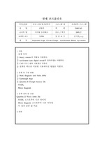
서론 - 설계 목적 ① binary counter의 역할을 이해한다. ② synchrnous type digital circuit의 설계과정을 이해한다. ③ CAD 프로그램의 사용법을 ... 학기 2005/2 교과목 코드 51956 담 당 교 수 김기만(교수님) 제 목 Sequential Logic Circuit Design ; Synchronous Binary up-counter ... 서론 - 설계 목적 ① binary counter의 역할을 이해한다. ② synchrnous type digital circuit의 설계과정을 이해한다. ③ CAD 프로그램의 사용법을
되고, 스위치를 GND로 두면 UP counter가 된다. 4. 10진 카운터(counter) 10진 카운터는 0에서 9까지 10개의 상태를 카운트하는것으로 10진수를 2진 코드로 ... D플립플롭의 출력은 B와 C가 1이고 A가 1에서 0으로 변할 때 상태를 1로 바꾸고 B, C가 0이고 A가 1에서 0으로 변하면 D플립플롭의 출력이 0이 됨을 알 수 있다. ... C플립플롭의 출력은 B플립플롭의 출력이 1에서 0으로 변할 때 상태를 바꾼다. 4.
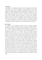
The term ‘bean-counters’ was used with specific reference to the conventional roles of management accountants ... Introduction Conventional roles of management accountants, who have sometimes been described as ‘bean-counters ... Thus, this essay will give an explanation of what ‘bean-counters’ means and the reason why the term has
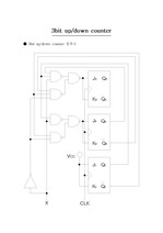
3bit up/down counter --------------------- ● 3bit up/down counter 블록도 ● 3bit up/down counter 진리표 A B ... 1 0 1 X 0 X 1 1 X 1 1 1 1 X 0 X 0 1 X 1 1 1 0 1 1 0 X 0 X 0 X 1 1 0 0 0 X 1 X 1 X 1 ● 3bit up/down counter ... C X A+ B+ C+ JA KA JB KB JC KC 0 0 0 0 1 1 1 1 X 1 X 1 X 1 0 0 1 0 X 0 X 1 X 0 0 1 0 0 0 0 0 X 0 X X
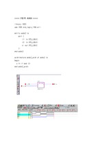
(7 downto 0); ch: out STD_LOGIC ); end parity_check; architecture parity_check_arch of parity_check is ... ); end DFF; architecture DFF_arch of DFF is begin process(d,ck) begin if ck'event and ck = '1' then ... Fullsub11 is begin process (x3,x4,ci2) begin if x3>x4 then if ci2='0' then co2
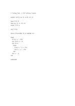
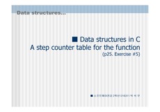
■ Data structures in C A step counter table for the function (p25. ... 2]={1,2,3,4}, bbb[2][2]={1,2,3,4}, ccc[2][2]={0,0,0,0}; mult(aaa, bbb, ccc); printf( \n\n%d ,count); ... { count++; c[i][j]+=a[i][k]*b[k][j]; count++; } count++; } count++; } count++; } main() { int aaa[2][
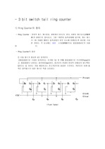
단순한 ring counter의 설계가 아닌 제어논리를 포함한 counter의 설계라는 것을 잊은채 실험을 하였고 따라서 문제점이 그곳에 있었던 것 같은데 실험하는 상황에서 Preset과 ... 마지막 플립플롭의 output 을 맨 처음플립플롭의 D 입력에 연결을 시켜 switch tail ring counter를 완성하였 다. ... - 3 bit switch tail ring counter 1) Ring Counter의 정의 - Ring Counter : 전자적 펄스 계수장치. 환형계수기라고도 한다.
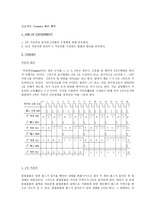
그림에서 보듯 클럭 펄스가 공동으로 각 플립플롭에 들어감을 확인할 수 있다. - 비동기식 카운터(Asynchronous counter=Ripple counter): 한 플립플롭의 ... . - 동기식 카운터(Synchronous counter): 여러 개의 플립플롭이 변경되어야 할 때 상태 변화 가 동시에 발생하도록 공통 클럭 펄스에 의해 동기화된 플립플롭의 작동위의
Normally, electrochromic devices (ECDs) consist of EC materials, an electrolyte, and counter electrode ... In this paper, we used and compared the counter materials of ferrocene and carbon electrode for the dimethyl ... The counter material is essential for improving ECD properties such as long-term switching stability
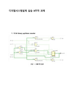
N bit binary up/down counter 그림 SEQ 그림 \* ARABIC 1 : 모듈구현 결과 그림2 : waveform (eup = 1) 그림3 : waveform ... 그림8 : 모듈구현 결과 그림 9 : waveform 결과분석 및 고찰 첫번째 문제에서는 hierarchical 하게 카운터를 구현하기 위해서 N bit binary up down counter를 ... cascadable하게 구현했다.
그림 SEQ 그림 \* ARABIC 2. 4-bit binary ripple counter -동기 counter 동기 counter는 counter를 구성하는 모든 flip-flops의 ... 그림 2와 같은 형태의 구조를 갖는 counter를 특별히 ripple counter라고 하며 대표적인 비동기 counter이다. ... 실험 목적: 1) counters: -counter의 구조와 동작원리를 이해한다 -비동기/동기 counters 2) state machine design -mealy and moor
실험 목적동기식(synchronous), 비동기식(asynchronous) 카운터(counter)에 대하여 공부한다.2. ... 즉, “입력 펄스의 개수를 기억해서 저장, 숫자를 세는 것”(count)이 중요하게 되는데, 이러한 기능을 가진 디지털 회로를 카운터 회로 라고 말한다.(1) 비동기식 업 카운터그림
실험 결과 (1) 실습1 설계 조건 4-bit up counter의 출력 값을 single FND에 표시 1. up counter 설계 2. static 7 segment를 모듈화해서 ... 사용 code Combo box실험결과 (2) 실습2 설계 조건 Design counter with Piezo 동작 검사 1.TOP module 설정 2. ... 실험2) Design counter with Piezo 실험2에서의 코드해석은 실험결과 주석 부분을 참고한다.
사용 code simulation (2) 실습2 설계 조건 Design counter with Piezo 동작 검사 1.TOP module 설정 2. ... array에 -128 ~ 127 로 표현하는 모듈 설계 조건 *코드가 자꾸 WARNING이 떠서 시뮬레이션을 확인할 수 없었다. code (6) 실습6 4-bit up-down counter의 ... 실험 방법 (1) 실습1 설계 조건 4-bit up counter의 출력 값을 single FND에 표시 1. upcounter 설계 2. static 7 segment를 모듈화해서
Mealy Machine for the Serial I/O code converter 6.74LS193A counter 참고 문헌 전전설 교안 ... with a synchrounous reset (5) Mealy Machine for the Serial I/O code converter (6) 74LS193A counter 참고 ... converter (5) 74LS193A counter < 74LS193의 Datasheet (Pin배열) > VCC : 전원을 공급하는 부분 GND : 접지단자 < Input >
목적 이 장에서는 순서논리회로의 기본적인 응용회로가 되는 시프트 레지스터 (Shift register), 링 카운터 (Ring counter), 존슨 카운터(John counter) ... 다음 그림 6은, Logic Works를 활용하여 시뮬레이션 한 결과이다. △ 그림 6 Ring counter 시뮬레이션 결과 CLKQ _{3}Q _{2}Q _{1}Q _{0} 1 ... 다음 그림5는 병렬 입력/병렬 출력 레지스터를 나타낸다. ◁ 그림 5병렬 입력/병렬 출력레지스터 (2) Ring counter 링 카운터는 각 순서의 상태에서 하나의 플립플롭을 사용한다