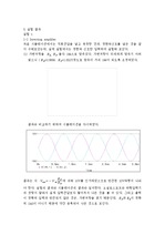
이론 1.1 Operation amplifier (Op-amp) Operation amplifier (Op-amp)는 그림1과 같이 5개의 단자를 가진 구조로 되어 있다. ... 이 식에 따라 입력 전압 과 의 차이에 를 곱한 값이 출력 전압 값이 되므로 입력 전압에 비해 출력 전압이 증폭되기 때문에 Amplifier라고 불린다.
① 이상적 연산 증폭기 (Ideal Operational Amplifier)연산 증폭기는 집적회로(IC) 칩으로, 여러 트랜지스터, 저항으로 구성된 하나의 작은 패키지 형태이며 5개 ... ② 실제 연산 증폭기 (Real Operational Amplifier)실제 연산 증폭기라고 해서 이상적인 연산 증폭기와 큰 차이점이 있는 것은 아니다.
결론 및 토의 이번 실험은 operational amplifier를 이용해서 instrumentation amplifier회로를 설계하고 시뮬레이션 해보는 실험이었다. ... 실험 방법 및 예상 실험 결과 실험1] Op Amp - instrumentation amplifier [1-1] 3개의 operational amplifier를 사용하여 instrumentation ... 전자전기컴퓨터설계실험3 4주차 결과보고서 학과 : 전자전기컴퓨터공학부 학번 : 이름 : OP AMP-Instrumentation amplifier circuit 실험 목표 Operational
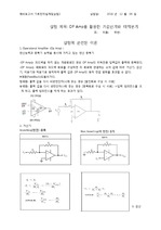
실험 방법 및 예상 실험 결과 실험1] Operational Amplifier [1-1] 실험에 사용할 741 operational amplifier에 대한 data sheet를 구하시오 ... 아래는 741 operational amplifier의 회로도이며 향후 전자회로2에서 배울 내용임. ... 전자전기컴퓨터설계실험3 3주차 결과보고서 학과 : 전자전기컴퓨터공학부 학번 : 이름 : OP AMP 실험 목표 Operational Amplifier(OP Amp) 를 사용하여, 3개의
실험 이론 (1) 연산증폭기 (Operational amplifier) 여러 부품으로 이러어진 회로를 하나의 칩으로 집적화 한 것이다. ... OP Amp - Operational amplifier 연산증폭 장치 6. 저항 - 증폭비를 설정할 때 이용한다. 실험에서 1kΩ 10kΩ 저항을 사용 7. ... - 예비 보고서 - 실험 제목: 증폭기(Amplifier) 실험 과목명 : 기계 공학 기초 실험 제출일: 실험일자: 실 험 조 명 : 책임 수행자 : 공동 수행자 : 형 식 / 2
Op Amp (Operational Amplifier, 연산 증폭기)(1) 연산증폭기는 두개의 입력과 한개의 출력을 가지는 직류 연결형 전압 증폭기 이다. ... Op Amp, Inverting amplifier, 연산 증폭기, Gain, 저항, 비반전회로이론적 배경 1. ... Inverting amplifier 의 원리를 통해 그래프의 위상이 어떻게 바뀌는지, 또 반전을 여러번 거쳤을때의 위상과 그 output의 Gain은 어떻게 되는지를 살펴본다.Keyword
The basic operation of this amplifier is also similar to a summing amplifier. ... Op-amp TOC \o "1-3" \h \z \u Hyperlink \l "_Toc37310156" 1.Theory Hyperlink \l "_Toc37310157" 1-1Operational ... It is a circuit that obtains output voltage through the integral operation of input signal.
⚫ Explain about your bias circuit configuration of the BJT amplifier동작점 Q는 process, voltage, 온도 변화에 대해서 ... Configuration을 설명하면, 먼저 negative feedback을 이용하여, thermal runaway를 방지하고 operating point를 안정화 한다.
Object Through this experiment, we will understand the operating principle of the cascode amplifier using ... As so, the cascode amplifier also has the purpose of increasing the output resistance and operating like ... Cacode amplifier 1.
In this experiment, the operating principle of the common gate amplifier is examined, and the voltage ... In this experiment, we will examine the operation principle of the source follower and confirm the voltage ... This time, an experiment is conducted on the remaining basic amplifier structure, the common gate amplifier
Operating principle Cascode amplifier Compared to a normal single amplifier, this combination has one ... Operating principle 555-timer A desired operation is performed by comparing the divided voltage with ... Through this, the amplified signal is output without loss.
After that, through common gate amplifier experiment, we will examine the operating principle of the ... Object In the source follower experiment, we will examine the operation principle of the source follower ... the magnitude of the output signal in the large signal is reduced by VGS compared to the input., the operation
impedance of BJT common base amplifier and emitter followers.3) To compare the common base amplifier ... 실험과정(1) Calculate the parameters and find the operation point for given DC biased CBa) Build the circuit ... undistorted waveform( Vout ) appears, on the [Table8.4].g) Calculate the maximum Vpp which BJT can be operated
Amplifier > The ideal operational amplifier is a simple model of an operational amplifier that is linear ... Theories 1) Operational Amplifier The operational amplifier is an electronic circuit element designed ... Circuit and Nodes of the Operation Amplifier > < An Operational Amplifier Including Power Supplies >
Using Operational Amplifiers Many of the operational amplifier circuits that perform mathematical operations ... The ideal operational amplifier is the simplest model of an operational amplifier. ... operational amplifiers are equal.