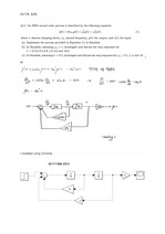
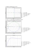
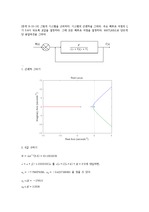
] (a) I modeled using Simulink. (b) The Wn was fixed at 1 and σ = 0, 0.2, 0.5, 0.8 and 2.0 10.0 values were entered from figure 1 to 7 yello(σ=0), blu..
제어공학 텀 프로젝트 (1) 이론 내용 조사 및 정리 ① 근의 궤적 (Root Locus) 1+KG(s)=0 식에서, K값에 따른 all possible roots의 그래프를 Root ... 그리고, 이것에 기반한 design method를 Root Locus Design Method라 한다. ② PI Controller의 계수 ( K_P K_I) PID 제어기는 feedback제어기의 ... Locus라 한다.
Project Assignment Design of Lead & Lag Compensator Using Root Locus Consider the following problem of ... Design a lead compensator using the root locus technique so that the dominant poles are at -2+2j, -2- ... 즉, 밑의 K가 존재하는 Term이 10이 되면 된다. ∴ ∴ ∴ < 매트랩 코딩 > %root locus numL=[1 1];% 전달함수의 분자 Term denL=[1 4 8];%
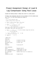
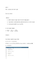
Root locus using Matlap ⅰ) K _{1} =2 num=1; den=[1 2 0]; K=0:0.01:1000; r=rlocus(num,den,K) plot(r,' ... K _{1} s}한편, 우리는 K _{1}값을 모르므로 K _{1}값을 2에서부터 3까지 0.2씩 증가시키며 가정하여 Root locus를 구해보도록 한다. 3rd) Calculate ... Locus가 원점으로부터 시작하여 ±90 DEG 점근선을 따라 발산함을 볼 수 있다.
The root locus method 1) 제한요소 (1) 경제적 제한조건 : 모터에 인가되는 증폭기의 용량을 가능한 적게 하여 비용을 낮게 한다. ... The root locus method 1) 제한요소 2) 설계과정 (1) Controller, Damping ratio 설정 (2) 설계과정 (3) 결과 3) 결론 (1) Controller
; rlocus(sys); 이때의 rmT _{s}는 0.0249초이고, Root Locus에서 dominant pole의 damping ratio는 0.798이다. ... 제어기를 추가했을 때의 Step Response와 Root Locus는 다음과 같다. nump=[1 147]; denp=[1]; sysp=tf(nump,denp); step(sys) ... Locus 그래프이다. rmT _{s}가 약 0.461초이므로, 위의 주어진 목적과 제한 요소를 맞추기 위해 제어기를 추가하였다.
실험목적 P제어기, PD제어기, PI 제어기에서 Root-Locus 선도를 그려보고, 시스템거동을 파악한다. ... 실험결과3.1 비례 제어 시스템의 Root Locus (P제어 시스템) P제어 시스템에서는 실험값과 이론값의 차이가 나타났다. ... Locus (PD제어 시스템) PD 제어시스템에서는 Kd 값이 커질수록 OS%가 줄어드는 것을 확인할 수 있다.
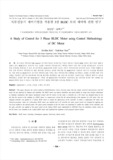
locus method to the derived system. ... three-phase BLDC motor was modeled and a PI controller for motor speed control was designed by applying the root
Root locus at PI co. 그러나, steady state값이 1이 아닌 0.9에 수렴하므로 0.1정도의 가 남아있음을 알 수 있다. ... 그려진 root locus를 보면, 근이 right half plane에 없고 steady state상태에서 수렴하면서 stability함을 알 수 있다. ... Root locus at P controller) (Figure 15.Informatin for tansient response at No controller) 어떤 제어기를 사용하기로
Sketch the root locus for the forward transfer function, 6. ... The open-loop transfer function of a unity feedback system is given by Sketch the root locus of the system ... locus crosses -axis.
Chapter 7 Lead Compensator Design□ Objective- Learn lead compensator design method based on root locus ... Chapter 8 Lag Compensator Design□ Objective- Learn lag compensator design method based on root locus
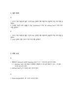
설계 A목적 :DC모터의 위치 제어기 설계Root locus method 제한조건1) 증폭기의 용량 즉 K값을 가능한 적게 하여 비용을 줄인다.2) 가능한 빠른 시간내에 목표치에 도달하도록 ... 그래서 Response time과 Transient Behavior(과도 특성)은 중간에 맞추어 root locus method 활용.K=155.1 일때에,Settling time=
저는 Routh-Hurwitz, Root Locus를 배우면서 시스템이 안정된 구간에서 작동하는지 판단할 수 있는 지식을 얻었습니다. ... ‘설비 시스템 제어 능력’ 자동제어 수업을 들으면서 Routh-Hurwitz 판별법, Root Locus, PID 제어기 설계 등을 배웠습니다.
방정식과 기계적 방정식을 계산하고 Matlab과 simulink로 상태 공간 행렬로 변환했습니다. controllerable 확인 후 Ackermann 법칙과 symmetric root ... locus를 도출하여 제어기를 설계하였고, observable한지 계산한 후 Estimator도 설계하여 각 성능과 합친 성능을 비교하여 상태 공간을 이용한 제어 시스템 설계를 학습하였습니다