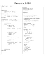
TTL 7457 회로는 입력된 클럭을 60 대 1로 분주하는 주파수 분주기 회로로서 내부에 구현된 3개 카운터의 연결을 조합하면 여러 가지 비율의 주파수 분주를 구현할 수 있다. TTL 7457 회로에는 6진 카운터와 5진 카운터와 2진 카운터가 포함되어 있다. 6진 ..
- TTL 7456 회로는 입력된 클럭을 대 로 분주하는 주파수 분주기 회로로서 내부에 구현된 3개 카운터의 연결을 조합하면 여러 가지 비율의 주파수 분주를 구현할 수 있다. - TTL 7456 회로에는 아래 그림과 같이 두 개의 5진 카운터와 하나의 2진 카운터가 포..
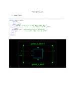
divider counter module counter module을 모은 top module RTL Map ... RTL MAP test_bench 4bit-up counter RTL MAP test bench 4bit down counter RTL MAP test bench test bench frequency
[사진 17] Clock frequency divider의 설계 [사진 18] Clock frequency divider의 시뮬레이션 결과 이론식과 data sheet, PSpice ... 상의 설계를 바탕으로 PCB board에 clock frequency divider를 [사진 19]과 같이 제작하였다. ... Clock Frequency Divider Using D-Flip/Flop (04) 2.3. Analog Computer (05) Ⅱ. 본론 (07) 1.
배경 ..PAGE:3 Divider란? ... 배경 ..PAGE:4 2.1 설계 목표 및 사양 Output Frequency:200MHz Reference Frequency: 16.66MHz 목표 분주비: 12분주 ..PAGE: ... 5분주.PNG ..FILE:5분주회로.PNG ..FILE:6분주.PNG ..FILE:6분주회로.PNG ..FILE:8분주.PNG ..FILE:8분주회로.PNG ..FILE:PLL DIVIDER
Feedback loop에 Divider를 추가하여 noise 없는 저주파 상태에서 Phase Detect를 하는 것이다. ... . ∴ 을 0.01으로 고정하면이 550Ω일 때 non-running frequency() 가 50kHz가 된다. ... 실험회로 및 시뮬레이션 결과 ↓ 실험 PLL 회로도 실험을 진행하기 위한 값 설계 Design , to make 50(kHz) for VCO frequency with = 1kΩ,
구조와 고속 Frequency Divider에 대해서 공부하고 있습니다. ... 부분을 맡아서 설계를 진행하고 있습니다. 60GHz 대역에서 쓰이는 다양한 구조의 VCO 구조를 공부한 뒤에 Push-push VCO 설계와 추가적으로 Injection locked divider
The types of filters are divided according to the frequency bands. low pass filter passes through the ... a certain frequency band, the band stop filter rejects certain frequency band. ... Therefore, the desired frequency band can pass by increasing the gain and the unwanted frequency band
회로에 Voltage divider를 적용하면 이므로 전달함수는 이다. 또한 이때 cut-off frequency 이 된다. ... 다음으로 RC회로에 같은 방법으로 Voltage divider를 적용하면 전달함수와 cut-off frequency는 다음과 같다. ... 이 때 조건은 cut-off frequency가 4kHz가 되어야 한다.
First, when j=0, divide the case by using the if-else statement as the first input (i=0) and the rest ... First, I changed the coefficient of filter to match the sampling frequency used in our project. ... LPF follows the following formula, and the sampling frequency in our project is .
(due to increased attenuation of higher frequencies) - Fractional bandwidth : bandwidth divided by the ... Operating Frequency (=Resonance frequency) - Operating frequency (Resonant frequency) is the frequency ... operating frequency : The strongest frequency within the bandwidth is the operational frequency. 2)
Operating principle 555-timer A desired operation is performed by comparing the divided voltage with ... The goal is to implement some scales using each different frequency by applying a different load using ... project aims to design an electronic Piano Using a 555-Timer as a square wave oscillator in the audio frequency
Circuit As it is difficult to measure current directly with an oscilloscope, was measured and then was divided ... Its frequency dependence becomes heavier especially for a carbon resistor given a high frequency domain ... shows the frequency response of the RLC circuit.
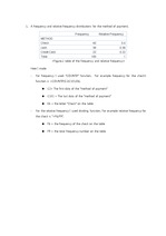
I used dividing function. ... A frequency and relative frequency distributions for the method of payment. ... Frequency Relative Frequency METHOD Check 40 0.4 cash 38 0.38 Credit Card 22 0.22 Total 100 1 How I made
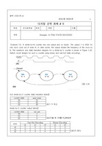
In other words, the output divides the frequency of the clock by N. ... The waveform and state transition diagram for a divide-by-3 counter is shown in Figure 3.28. ... 디지털 공학 과제 # 9 학과 전자공학과 학년 학번 이름 주제 Example 3.6 FSM STATE ENCODING Example 3.6 :A divide-by-N counter
AFM uses a "bi-cell" PSPD, divided into two halves, A and B. ... LFM requires a "quad-cell" PSPD, divided into four quadrants, A through D. ... Frequency 298.29× 10 ^{-3}Hz -AFM Prove Cantilever data: Technical Data Nominal Value Specified Range
Orientation Concept Concept The property of discontinuity Orientation Continuity or Length Spacing or Frequency ... Experiment 01 The Property of Discontinuity Orientation Definition Theory 02 Joint Joint is a fracture dividing
과 V_2를 가변저항을 이용한 voltage divider로 구성하고, V_2를 고정한 후 V_1 값을 변화시키며 출력전압을 측정한다. 2. ... V_1 1. , V_2, V_3를 가변저항을 이용한 voltage divider로 구성하고. V_2, V_3 전압을 고정한 후 V_1 출력전압을 측정한다. R32. ... 일단 3에서의 전압( V _{+})은 R3와 R4의 voltage divider로 작용하므로 V _{+} = {R4} over {R3+R4} V _{2} (2.1) 이며 Opamp의
It was analyzed by dividing it into 5 cases. ... Start Frequency는 100Hz, Stop Frequency는 20Hz 그리고 Steps은 30으로 설정한다. 4. ... Basic tools for electronic measurement, system dynamics and time-frequency domain measurement Report