of a MOSFET commonsource amp 3) To study the purpose and the effect of the source degeneration 2. ... Repeat step 2. d) Draw the drain characteristic curves with source degeneration. ... 실험(3):Common source amplifier a) Replace the VGG with the function generator as shown in Figure 1.4.
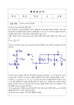
2. 고찰 사항① 실험회로 2에서 입력 쪽과 출력 쪽의 커패시터를 커플링 커패시터라고 부른다. 커플링 커패시터는 직류(DC)를 차단하고 교류(AC)를 통과시키는 목적으로 사용된다. 이러한 커플링 커패시터는 증폭기의 입/출력단에 연결하여 사용하는데, 이는 입력에서 들어오..
요약 이번 실험에서는 NMOS의 특성을 이해하고 Common Source Amplifier를 설계, 구현, 측정하는 실험을 하였다. 0.04의 작은 입력전압으로 1.5의 큰 출력전압 ... Common Source Amplifier의 주파수 응답에선 3dB frequency는 100Hz보다 약간 큰 값과 50kHz보다 약간 작은 값을 가지고 Unit gain frequency는
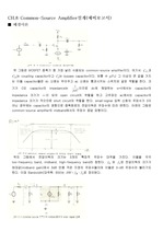
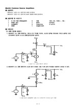
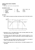
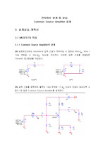
CH.8 Common-SourceAmplifier설계(예비보고서) ■ 배경이론 위 그림은 MOSFET 증폭기 중 가장 널리 사용되는 common-sourceamplifier이다. ... 설계 ① 과 같은 회로를 이용하여 아래의 사양을 만족하는 common-sourceamplifier를 설계하려고 한다. ... 아래의 그림은 common-sourceamplifier의 midband에서의 주파수 응답 파형이다. 위의 그림에서 전압이득의 크기는 3개의 특징적 주파수 대역을 가진다.
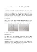
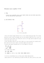
Common source amplifier 의 특성 1. ... 목표 Common source amplifier를 cadence tool을 사용하여 설계하고 입력, 출력 파형의 관찰을 통해 소자의 각종 파라미터에 따른 특성을 파악한다. 2. ... 실제 전체 입력저항 (6) MOSFET Common source amplifier 요약 전달 특성 곡선 상에서 E-MOSFET(n채널) 동작 ? ? ?VDS = VDD-RDID ?
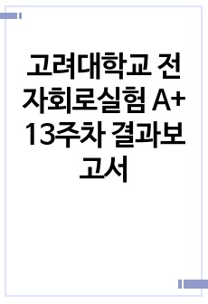
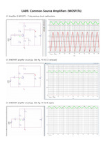
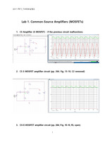
Mosfet Common Source Amplifiers ■ 실험목적 -MOSFET 공통 소스 증폭기에 대해 조사한다. ... 측정된 값을 이용하여 증폭 이득 값을 계산하여 표 7-2에 기록한다. ■ Pspice는 simulation 회로구성 그래프 V i V i ■결과 레포트 ? ... 오실로스코프의 ch1 단자는 입력 단에, ch2 단자는 출력 단에 연결한다. 4. 입력 및 출력 파형의 Vp-p 및 위상변화를 측정하여 표 7-1에 기록한다.
따라서 Simulation과는 전혀 다른 결과가 출력될 수 있다. 3.3.1 Single-stage common-sourceamplifier Figure SEQ Figure \* ... 따라서 3.2.2의 회로에서는 14Hz~500kHz의 Bandwidth frequency를 갖는다. 3.3.3 Common-source + common-source + source ... 따라서 이 회로의 Bandwidth frequency는 12Hz~390kHz이다. 3.3.2 Common-source + source follower (CS-SF amplifier)
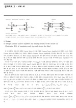
Design 1) Design common source amplifier and biasing circuits in the circuit (a) (Determine W/L of transistors ... HW #1 1. ... Compare the results with hand-calculated result in 1.
즉, commonsource stage는 주로 증폭 역할로써 사용된다. 2. 2단 Common-SourceAmplifier 동작 원리 2단 Common-SourceAmplifier는 ... 이 때, degeneration 저항을 source단에 달아주게 되면 입력 bias의 변화에 따른 , 의 급격한 변화를 안정시킬 수 있지만, GAIN은 감소한다. ... CommonSource Stage는 위와 같이 되어있으며, saturation region이고 일 때(channel length modulation을 고려할 때), small-signal
I.IntroductionI.1.Purpose본 실험에서는 N-type MOSFET 기반의 common-sourceamplifier에 여러 소자들 – signal resistor, ... source resistor, source capacitor – 을 각각 추가하거나 input의 주파수 또는 진폭에 변화를 준 뒤 회로의 parameter와 출력을 관찰함으로써 그 ... Common Source Amplifier with a Source ResistorII.3.A.Exper. 3-1) Without a Source Bypass CapacitorFigure
> To design a common-emitter amplifier, we added some resistors and a capacitor to the common emitter ... The current flow from the emitter to the collector can be viewed as a current source tied between these ... Source The goal of the third experiment is to build a current source and to observe changes while varying
이 실험을 통하여, 전자회로 시간에 배웠던 Common source amplifier에 대해서 더 정확히 알 수 있었다. 왜 이러한 저항을 달아줬는지(바 ... 요약 설계한 Common source Amplifier가 PSPICE의 결과와 비교한 결과 오차율은 2.18%, -5.68%, 0% 를 보였다. 6% 미만의 오차를 보였으므로 설계는 ... 그 다음 설계한 Common source Amplifier가 PSPICE의 결과와 비교한 결과 오차율은 -2.28%, 6.01%, 0% 를 보였다. 6% 이하의 오차를 보였으므로 이
315.08Hz unit gain frequency: 16.8Hz, 27MHz (D) Commonsource Amplifer와 CommonSource Amplifer with Source ... 계산결과 대략 R _{S}=100 kΩ이다. - C _{1}, C _{2}=100nF 그리고 C _{s}는 10uF으로 정한다. ... Unit Gain frequency는 low frequency band에서는 C_c1, C_s, C_c2에 의해 영향을 받고, High frequency band에서는 C_gs와 C_gd에
C_c1= C_c2= 1 ㎌ , C_S= 10 ㎌ 와 같이 설계한다. ... SourceAmplifier의 특성 변경 (A) 그림 7-1의 입력단 Capacitor( C_c1)를 10 nF 으로 바꾼다면 gain의 주파수 특성이 어떻게 될 것인가를 정성적으로 ... (D) Common Source Amplifier와 Common Source Amplifier with Source Degeneration을 비교하여 R_s을 연결할 때 장점과 단점을