gain of the cascode amplifier is × . ... That is, the advantage is that the voltage gain of the cascode amplifier is very large compared to the ... voltage gain of the common source amplifier.
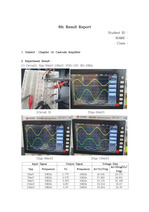
Result Report Point : (1) Discuss the advantages and disadvantages of a cascode amplifier over a common ... source amplifier. -> The advantage of cascode is that the voltage gain is greater than that of the common ... disadvantage in that the output resistance increases. (2) How much has the output resistance of the cascode
경상북도 https://www.ieee.li/pdf/essay/cascode_amplifiers.pdf https://www.circuitstoday.com/push-pull-amplifier ... 제작 5.14 ~ 5.26 기판 납땜 5.27 ~ 5.30 최종 보고서 작성 , PPT 제작 References https://www.electronics-tutorials.ws/amplifier ... , C2, C8 : AC coupling capacitor 로 입력 신호와 앞에서 증폭된 신호들의 DC 성분을 차단하고 small signal 을 인가하는 역할을 한다 .
The goal is to find the input/output characteristic curve of a cascode amplifier and to verify the voltage ... Related theories The cascode means a two-stage amplifier that consists of a common-emitter stage feeding ... The graph on the right is the input/output transmission characteristic curve of this cascode amplifier
In this experiment, the input-output characteristic curve of the cascode amplifier is obtained, the concept ... Overview of the experimentIn this experiment, the operating principle of the cascode amplifier using ... Cascode amplifiers are widely used because they can obtain higher voltage gains than common source amplifiers
Reference [1] https://www.allaboutelectronics.org/cascode-amplifier-using-mosfet-explained/ [2] https ... 그리하여 RD의 값을 높일 수 있는 방법인 cascode을 선택하였다. cascode의 common gate부분의 vout쪽에 저항 RD를 달아 Gain값을 조절하였다. ... 첫 번째로 Cascode MOSFET를 구현할 때 Vin를 M1에 넣어 gain를 얻었지만 cascode의 역할을 회로가 하지 못하였다. cascode의 원리를 이해하고 나니 M3에
경상북도 https://www.ieee.li/pdf/essay/cascode_amplifiers.pdf https://www.circuitstoday.com/push-pull-amplifier ... References : https://www.electronics-tutorials.ws/amplifier/amp_2.html https://alltransistors.com/adv ... CE Amp(Common Emitter Amplifier)와 push-pull amplifier를 이용한 음성증폭기 제작이 이번 프로젝트의 목표이다. 3.
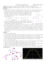
크면 클수록 좋기 때문에 cascoding을 통해 출력저항을 높인다. ... 이 높아진 출력저항은 current source load가 amplifier에 연결되었을 때 gain이 증가하도록 해준다. ... 따라서 출력저항의 값이 증가됨을 알 수 있다. ideal current source의 저항은 infinity이므로 current mirror로 구현한 current source의 출력저항은
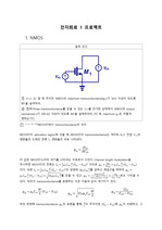
수 있도록 C1의 값을 매우 크게(10F) 하였다. ... Vin에 인가되는 small-signal과 M1의 게이트 노드 사이에 커패시터 C1을 추가하여 dc분석을 할 때는 Vin과 M1이 분리되지만, 소신호분석을 할 때는 short 취급될 ... 그리고 current source를 설계하실 때 실제 rg를 몇으로 설계하셨는지, 그리고 저항값의 변화에 따라 전류에는 어떤 변화가 생길지에 대해 언급해주시면 더욱 좋은 2차보고서가
CAD tool을 활용한 schematic design 및 simulation 검증 과정을 통해 회로 설계 과정에 대한 전반적인 흐름을 파악한다. ... 제목 : Fully-differential operational Sample and hold amplifier design2. ... 설계 목적주어진 사양에 맞는 operational amplifier를 설계함으로써 기본적인 analog circuit의 구성 및 이해 능력을 배양한다.
Common-Source Amplifier with Active Load 마지막으로 Active Load를 포함한 Common ? Source Amplifier의 경우이다. ... 실험 목적 파워서플라이 DMM (C 측정만 제외) Wavegen 파형을 발생 (설정) 함 Trigger 채널로 받아온 신호의 기준을 설정 Horizental Dial X축을 조절 Vertical ... Conductance는 다음의 식을 통해 구할 수 있다. [ g _{m} = sqrt {2 TIMES {I _{d}} over {2} TIMES {W} over {L} TIMES mu _{n} C
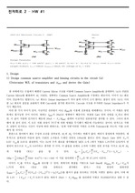
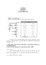
Design 1) Design common source amplifier and biasing circuits in the circuit (a) (Determine W/L of transistors ... Compare the results with hand-calculated result in 1. ... Compare obtained results with hand-calculated result in 1.
{beta _{D} R _{B} R _{E}} over {R _{B} + beta _{D} R _{E}}} ] CONG 1(전압 이득) 이론 캐스코드 증폭기 회로 (Cascode Amplifier ... 답 : 출처 http://mathphysics.tistory.com/334 https://m.blog.naver.com/PostView.nhn? ... 캐스코드 증폭기 회로의 정의 캐스코드 증폭기 회로란, 공통 베이스 회로(C-B 증폭기)와 공통 이미터 회로(C-E 증폭기)가 직렬로 연결된 다단회로이다.
전자회로2 설계과제#1 이 회로는 current mirror단을 포함하는 MOS Cascode Amplifier이다. ... 따라서 reference current와 같은 전류가 cascode단에 흐를 것이고, 이를 이용하여 분석하면 이득을 계산 해볼 수 있다. 1) Design problem: 주어진 parameter ... _{m3,4} = sqrt {2 mu _{p} c _{ox} ( {W} over {L} ) _{3,4} `I _{D~3,4}} =0.000316 다음으로 r _{0}값을 주어진 조건을
CE 증폭기 psipce 실험 결과 Midband Gain 28.092dB Upper 3db f H =548kHz Lower 3db f L = 465Hz V 25.388 문제 -2 cascode ... CE amplifier BJT 2N3904 type .model Qbreakn npn + Is =6.734f Xti =3 Eg =1.11 ... 증폭기와 Cascode 증폭기의 이득 및 대역폭을 계산하고 , PSPICE 모의실험을 해서 측정결과와 비교 하시오 . ( 강의자료 6-SSA-3, p.29~p.33) 문제 -1 CE amplifier
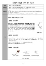
Cascode Amplifier ◆ 실험목적 ? Cascode 증폭기 회로의 기본적인 동작을 이해한다. ? ... 그림 4-4의 cascode 증폭기 회로를 PSPICE로 구성한다. 2. ... 수 있고 또, cascode 증폭기가 더 넓은 대역폭을 얻음을 알 수 있다.
실험으로부터 cascode 증폭기는 공통 이미터 증폭기와 같은 이득을 가지나, 더 넓은 대역폭을 가짐을 확인한다. ... CE 증폭기와 비슷한 이득과 더 넓은 대역폭을 가지는 증폭기 중에서 그림 4-1에서 보이는 회로를 cascode 증폭기라 한다. ... 이 값은 CE 증폭기에서 k배로 커지는 것보다 작기 때문에, cascode 증폭기는 더 높은 주파수에서 이득은 줄고 대역폭은 넓어지게 된다. ▶실험순서 1.
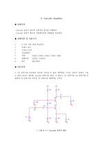
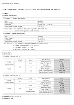
1. 설계 : Current Mirror + Cascode의 구조를 갖는 회로를 주어진 specification에 맞게 설계해본다. 2. 설계과정 (1) Design Specification ① Problem 1's Design Specification Gain 30..
Designed Parameters M1(W/L) M2(W/L) M3(W/L) M4(W/L) M5(W/L) M6(W/L) M7(W/L) M8(W/L) 100/0.25 7/0.2MOSFET을 cascode ... Electronic Circuit1 _ 전자회로1 EEE2050-전자회로1 Pspice를 이용한 Amplifier 설계 제출날짜 담당교수 정성욱 교수님 담당조교 나태희 조교님 조원 ... 100um Body of PMOS must be connected to VDD 1.2 Problem1 a.