기초전기실험 예비보고서 DC2 Resistorsand the Color Code dc 2. Resistors and the Color Code 1. ... What are the ohmic values and tolerances of the following commercially available carbon resistors? ... (실험값에 영향을 주기 때문.) ◇0점 조정 후 사용하여야 한다. 2.
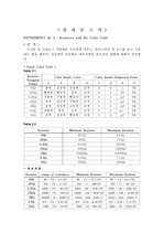
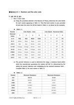
If not, how many resistors did not fall within the tolerance range?→모든 측정값이 오차범위인 5%이내이다.2. ... You can check by referencing Table 2.2 or comparing the percent tolerance to that listed in Table 2.1 ... (f) For the DMM measurements, are all the resistors within the specified tolerance range?
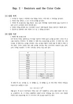
DC2 Resistorsand the Color Code1. 실험 목적 -디지털 ohmmeter와 아날로그 ohmmeter의 사용법을 숙지하고 익숙하게 다룰 수 있다. ... What are the ohmic values and tolerances of the following commercially available carbon resistors? ... -전류계와 전압계의 내부저항의 크기와 저항이 미치는 영향을 알 수 있다.2. 실험 이론 1. 저항의 색 코드 읽는 법 2.
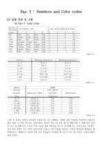
< 결 과 보 고 서 > EXPERIMENT dc 2 : Resistorsand the Color Code < 목 적 > 디지털 및 아날로그 저항계를 익숙하게 다루고, 레지스터의 ... What are the ohmic values and tolerances of the following commercially available carbon resistors? ... 1 0 10 5% 6.8Ω 파랑색 회색 금색 금색 6 8 10 5% 1KΩ 갈색 검정색 빨강색 금색 1 0 10 5% Table 2.2 Resistor Minimum Resistor
< 예 비 보 고 서 > EXPERIMENT dc 2 : Resistorsand the Color Code < 목 적 > 디지털 및 아날로그 저항계를 익숙하게 다루고, 레지스터의 ... 색 제1,2색띠 (제1,2숫자) 제3색띠 (승수) 제4색띠 (허용 오차) 검정색 0 100 ? 갈색 1 101 ±1% 빨강색 2 102 ±2% 주황색 3 103 ? ... 출처 : Electric Circuits (7th) 번역본, J.W.Nilsson&S.A.Riedel : P.101 전압과 전류 측정
●결과보고서 2 : Resistorsand the color code #. 실험 과정 및 결과 Part 2. ... ohmmeter, measure the resistance of each dc current scale of the VOM and record in Table 2.8. ... Then find each resistor in your provided kit and enter the colors for all four bands in Table 2.1, as
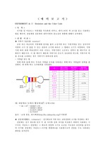
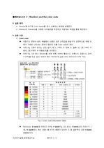
●예비보고서 2 : Resistorsand the color code #. 실험 목적 Resistor에 표기된 Color bands를 읽고 사용하는 방법을 실험한다. ... 아래 Fig. 1의 예시 Resistor를 보면 첫째 수부터 빨강(=2), 초록(=5), 검정(=1), 금색(=±5%)을 띄고 있다. ... Robert L.Boysestad and Gabriel Kousourou. prentice hall 전자용어사전, 월간전자기술 편집위원회, 1995.3.1, 성안당 저항색 구분. http
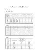
#2.Resistorsand the Color Code 1. 실험 결과 Part 2. ... Color Code Table 2.1 Resistor (Nominal Value) Color Bands - Color Color Bands ? ... 1.021 1.4 1.371 {1.4} over {1.371} =1.021 Table 3.6 R m (mS) 1kΩ 1.01 3.3kΩ 0.31 Calculat하면 V _{R}은 DC
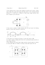
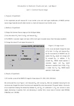
of the function generator, DC voltage of 800mV was input in reverse to the diode (see Figure 2-(a)). ... Due to the repeated charging and discharging of the capacitor, the signal shows nearly-constant DC like ... Observation on Rectification and Clamping Properties of Diodes under AC Current ******* Yun1, 2 1 Department
Cellphone=Resistor=720kΩ. 2. Connect DC supply to Vad. ... Increase DC voltage Vin from -2V to 2V with 0.5V scale, and measure DC voltage at Vout. ... Increase DC voltage Vad from 3V to 3.1V with 0.01V scale, and measure DC voltage at Vout andDC current
On a closed circuit with a DC voltage source and few resistors which are ich are not static. ... When there's a closed circuit containing DC voltage source of voltage V and a resistor with resistance ... At this time, we had set the initial DC voltage source to 3V and the DC voltage incremen voltage and
resistors are connected in series, parallel, and mixed to measure the resistance, and compared with ... Resistor color code Fig 2. Mixed Circuit Fig 3. ... 그리고 peak to peak amplitude을 2배 늘리게 되면, 파동의 진폭 또한 2배 증가한다. DC Offset은 파동을 y축 방향으로 이동시킨다.
With these resistors, 3 single-resistor circuit and 3 complex circuits are constructed and the resistance ... First, 3 different types of resistors are used, which are 220 , 1,000 , and 10,000 . ... Table 1 shows the circuit of each resistor connection case, and its equivalent resistance.
load is changed to pure resistor.(20) 2. ... Answer questions regarding following AC-DC-AC converter.(10) 1) Choose circuit which is most suitable ... 2) In order to operate as leading power factor how to provide gate signal and derive its output voltage
Especially we will utilize resistor as a load and measure in-out transfer curve. 2. ... In Figure 2, for all 3 resistors, we can find this tendency in the range , and . ... Purpose of Experiment In this experiment, we will measure DC in-out transfer curve and small signal amplification
기초전기실험 예비보고서 DC5 Series dc Circuits dc 5. Series dc Circuits. 1. ... For the series circuit of Fig. 5.2 record the measure values V _{1} ,V _{2} ,V _{3} and the current I ... Use measured values for the resistors. 실험을 하지 못하였으므로 Table 5.1행은 적지 못했다. 오른쪽 행은 PSpice로 측정하였다.