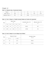
기초전기실험 결과보고서 DC6 Parallel Resistance dc 6. Parallel Resistance 1. ... 실험 결과 Part 1 Two ParallelResistors (a) R _{1``measured} `=`1182 OMEGA R _{2``measured} `=`2148 OMEGA ... Difference R_T (measured) 1100 OMEGA1083 OMEGA1.5454545 % 1080.7695 OMEGA Part 4 Different Levels of Resistance
기초전기실험 예비보고서 DC6 Parallel Resistance dc 6. Parallel Resistance 1. ... Which resistors of Fig. 6.10 are in series and which are in parallel? ... R _{3} -R _{4} R _{5} R _{6} R _{7} R _{8} 의`합성저항 Parallelresistors 1.
DC6 Parallel Resistance1. ... 실험 결과 Part 1 Two ParallelResistors Part 2 Three ParallelResistors Part 3 Equal ParallelResistors ... Part 4 Different Levels of Resistance Part 5 Open Circuits Part 6 Short Circuits2.
고찰)저항 R1, R2, 빈 도선을 병렬 연결했을 때의 결과를 확인하는 실험이다. 결론적으로 R1, R2,는 회로에 영향을 미치지 않았다. 두 저항과 도선은 병렬연결되었기 때문에 같은 전압이 걸리는데, 빈 도선은 저항이 매우 작기 때문에 전류는 빈 도선에 몰리게 되고 ..
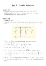
[1] 실험 목적1. 저항계 또는 옴의 법칙을 이용하여 병렬 연결된 저항들의 합성 저항을 결정해 본다.2. 병렬 연결된 저항들에서 개별 저항이 전체 합성 저항에 미치는 영향에 대해 알아본다.3. 회로에서 병렬 연결된 저항을 식별하는 방법을 배운다.[2] 실험 이론1. ..
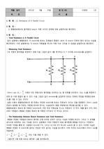
Resistance of A Parallel Circuit 2. 목 적 : ① 병렬회로에서의 총저항과 branch 저항 사이의 관계에 대해 실험적으로 확인한다. 3. ... 원 리 : - Total Resistance in A Parallel Circuit 앞의 실험에서 병렬회로의 각 branch에 흐르는 전류들의 총합은 IT로서 각 branch 전류의 ... and Total Resistance 병렬로 연결된 저항들과 회로의 총저항 간에 어떠한 관계가 있다는 사실은 자명해 보인다.
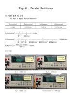
Parallel Resistance #. 실험과정 및 결과 Part 1. ... Different Levels of Resistance (a) 다음 회로를 구성하고 각각의 저항값을 측정하여 기록한다. ... Two ParallelResistors (a) 다음 회로를 구성하고 R_1와 R_2값을 측정하여 기록한다.
< 결 과 보 고 서 > EXPERIMENT dc 6 : Parallel Resistance < 목 적 > 병렬 회로망에서의 전체 저항을 옴계와 옴의 법칙을 적용하여 알아보고, 전체 ... 병렬 회로망에서의 각 저항의 관계에 대해서 실험을 통해서 공부해본다. < Part 1 Two ParallelResisters > (a) , Table 6.1 → 계 산 과 정 (e ... (f) How does the total resistance compare to the magnitude of the smallest of the parallelresistors?
Parallel dc Circuits 1. ... Given the milliammeter readings appearing in Fig. 7.8, determine the resistance R _{2}. ... (q) Using the applied voltage E and the measured current I _{S}, calculate the total resistance R _{T
DC6Parallel Resistance1. 실험목적병렬회로에서 저항계를 이용하여 저항을 측정하고, 옴의 법칙을 적용하여 전류를 계산할 수 있다. ... DC7Parallel DC Circuits1. 실험목적병렬회로에서 전류와 전압을 측정해본다. 키르히호프 전류 법칙을 적용해본다. 전류 분배 법칙을 적용해본다. 2.
And the resistance values ??of series, parallel, series & parallel connection ( (R _{1} +R _{2} )? ... Then we compared the theoretical and experimental values of series, parallel and serial+parallel connectio ... After viewing the resistance color code, we anticipate the resistance, and the resistance value was measured
3 .Simple Resistive (ircoits< Resistors in Series )0 Series -connected Circuit elements carry the Same ... elements have the same voltageacross thein terminals .,.combining esistovs in Parallel Req 소더Ri =ki ... Corrent .Req =ombining , k = k+ *resistorsinseries :< ResistorsinParallelI >0 Parallel -connected Circoit
Parallel R-C Network 1) Connect the DMM to the resistor to measure the resistance value and check whether ... Carging Network (Parallel Capacitors) 1) Connect the DMM to the resistor to measure the resistance value ... (current` PROPTO {1} over {resistance} ).
이코일의 inductance는 약 142 μH이고 series resistance는 약 0.16 Ω이다.②코일과 가변 콘덴서의 parallel resonance에 대한 equivalent ... 가변 콘덴서로출력 신호의 진폭을 최대로 하여 parallel resonance가 되도록 한다. ... 실험 내용 및 결과 분석실험1 : Equivalent conductance of parallel resonance circuit①[그림1]과 같이 ferrite core에 총 42바퀴의